|
|
This following pages are written by Ampetronic - the acknowledged leaders in loop amplification systems. It is written to be easy to understand and yet has some excellent diagrams and explanatory text showing you exactly how an Induction Loop system works.
 |
| WHAT IS AN INDUCTION LOOP?
To the technician this is a question that does not call for an answer. But not all hearing-aid users can be expected to know the answer. Many have not heard of such things, and do not have any idea of the great help an induction loop can be to them in compensating for their disability. So, the following explanation may be of some help in enabling non-technical persons to understand how an induction loop works. |
|
Audio
Induction
Loops
The most satisfying
Assistive Listening Technology
for Hearing Aid users
SPRING 2002
Full Member
INDUCTION LOOPS
THEIR PURPOSE & FUNCTIONS
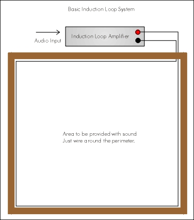
Most hearing aids nowadays have a switch marked M and T. Some even have M, MT and T. The M (microphone) position is for "normal" listening, that is receiving airborne sound via the microphone built in to the hearing aid. The T (telecoil) position is for receiving the sound via an induction coil which is built in to the hearing aid. For the induction coil to provide sound, a magnetic field is needed via which the sound is transmitted. This facility in hearing aids was introduced by a number of manufacturers many years ago and was then known as the "telephone" or "telecoil" position on the hearing aid switch. It was intended to make it easier for the hearing aid user to hear over the telephone, by picking up the sound via the magnetic field generated by the diaphragm coil in the receiver of the telephone. In recent years, however, induction loop systems have begun to be provided in public places such as churches, cinemas and theatres, and even in the home, and the T facility is used in such cases to listen inductively, without the interference of airborne background sound. The MT position which is provided on some hearing aids allows listening simultaneously both to airborne sound via the microphone and to inductively transmitted sound via the telecoil. It is well known that when an alternating current is passed through a wire, a magnetic field is generated around the wire. If a second wire is brought within this magnetic field, a corresponding alternating current is created within the second wire. In technical language, it is said that a current is “induced” in the second wire. Hence the term “induction”. This particular electromagnetic principle is the basis on which electrical motors, electrical generators and transformers operate. An induction loop for hearing aid purposes also operates in the same way. An induction loop system consists of an amplifier and a loop. The amplifier can be connected to a sound source such as a TV or radio, a PA system or a dedicated microphone. It then amplifies this sound signal and sends it out, in the form of an alternating current, through the loop. The loop itself consists of an insulated wire, one turn of which is placed around the perimeter of the room. When the alternating current from the amplifier flows through the loop, a magnetic field is created within the room. If a hearing aid user switches his hearing aid to the T position, the telecoil in the hearing aid picks up the fluctuations in the magnetic field and converts them into alternating currents once more. These are in turn amplified and converted by the hearing aid into sound. The magnetic field within the loop area is strong enough to allow the person with the hearing aid to move around freely within the room and still receive the sound at a good, comfortable listening level. Why an induction loop? In a noisy environment, or one in which reverberations and echoes are noticeable, we all find it difficult at times to hear and understand what is said. But for a person with impaired hearing, wearing a hearing aid, it can be almost impossible to hear and understand under such conditions. It is for these reasons that more attention is now being given to assisting hearing aid users by installing induction loops at the workplace, in schools, public halls, churches, theatres and many other types of public places. Social, welfare and public health authorities have also become increasingly aware of the need for induction loops in sheltered and residential accommodation. The new section M of the UK Building Regulations also specifies the need for such systems. A significant reason for preferring inductive loop systems in preference to IR or RF systems is that many locations exist where the issue of special receivers in not really possible, and only a facility build into the hearing aid can be used. Perhaps the greatest advantage, however, is that the sound comes to the user in a pure, undistorted form, not affected by the distance the listener is from the sound source, nor by any interfering background noises in the room, and is tonally corrected in the aid to the needs of the user. In the residential environment, many modern TV sets have a SCART socket, which permits a direct connection to a loop amplifier, so that the hearing aid user can listen, via the magnetic field of the induction loop, without other persons in the vicinity being disturbed by sound from the TV (or radio). Some induction loop amplifiers are also available with facilities for doorbell or telephone ringing signals to be transmitted over the loop in such an environment. The Regulatory environment The controlling standard for audio induction loops is EN60118-4, also known as IEC118-4. This defines the magnetic field strength and frequency response of the system. Equivalent standards operate in many other countries. Please consults the relevant standards authority. A Code of Practice, BS7594 exists in the UK and this incorporates useful extra information. In the UK, section M of the Building Regulations 1991, part M2, para’s 3.12 to 3.17 cover the requirements of these regulations. Many other countries.also have similar regulations. All Audio Induction Loop Drivers must be CE approved, to meet the new Interference Regulations (EMC).These standards impose strict controls on the performance of the equipment in the field of immunity, spurious emissions and electrical safety.
New requirements are also appearing
as a result of the Disability Discrimination
Act 1995. Again, similar legislation
is appearing in many countries.
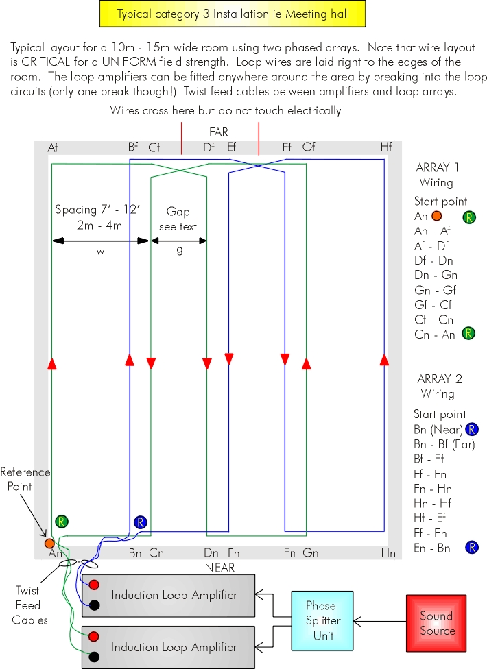
Notes on regulations: – Para 3.14 of Section M relates to the problems of spillover with induction loops which is sometimes very undesirable. Low-spillover systems Audio-Frequency Induction Loops create a magnetic field which is not constrained to the area of the loop installation. Normal systems using a perimeter loop create spillover so that they are clearly audible some 3 to 4 loop sizes away. There are many instances where this is unacceptable, such as in multiscreen cinema complexes, conference room situations, council chambers, multiple common rooms in sheltered housing, etc. AMPETRONIC have developed various technologies to minimise the loop spillover such that the above-mentioned situations can be easily resolved. Typically, in multi-screen cinemas we can provide a large portion of the seating in each auditorium with full quality sound while keeping the crosstalk from adjacent cinemas more than 40 db below the normal signal level for all the seats in the auditorium, ensuring compliance with film classification regulations. This is also applicable to conference rooms. Additional techniques can be used to create secure systems, where absolute secrecy is vital. The techniques all rely on using loop arrays that are designed to rapidly reduce the signal strength outside the loop layout pattern. For some of these patterns, there is a requirement to run two loop arrays, operated in phase quadrature, to obtain an even distribution without undesirable null areas. The design of the loop arrays is done with the help of a very advanced computer program, designed and written by Ampetronic. This program permits the full analysis of the total field envelope, computing the contribution from every section of loop cable, and allowing for different currents in various sections of the loop array if this is required to achieve the necessary performance. Some installers use direct injection of audio signals into loops (cross coupling) to create so-called low-spill systems. These methods are poor performers, relying in particular on an accurate vertical positioning of the hearing aid to obtain some level of cancellation. This is due to the curved nature of the magnetic field lines. We consider this to be an unacceptable restriction. AMPETRONIC will collaborate with the specifier or installer of the system to advise on the best layout, and will normally provide the detailed design. Consultancy The design and installation of Audio Frequency Induction Loops (AFILS) is a very specialised field, and is often outside the working knowledge of many specifiers and installers. This is especially true where specialised requirements have to be met, such as theatres with balconies, very irregularly shaped rooms, large buildings such as sports halls, Cathedrals and similar size churches, concert halls, low-spill systems as noted above. Additional problems occur due to the large amounts of steel incorporated in modern structures, which cause significant losses. AMPETRONIC has developed a sizeable fund of knowhow on the design and installation of such complex systems. AMPETRONIC will not undertake actual installation contracts as we work exclusively as consultants and suppliers to system specifiers and installation companies. To assist with the design of the loop layouts, Ampetronic uses a very advanced computer program, designed and written in-house. This program permits the full analysis and computation of the entire spatial magnetic field generated by the complex loop layout. Full provision is made for designing phased arrays, multiple loops with different currents, etc. Depending on the requirements, the support can range from advice given during a telephone call to extensive design work, using architects’ drawings and site surveys and trials, demonstrations, commissioning and quotations. Apart from the limited duration telephone support, we are normally willing to look at drawings and offer advice without charging, but extensive design work and the production of drawings will be a chargeable activity. Amplifier / Driver selection Selection of the correct Induction Loop Driver is very important if optimum results are to be achieved. The table below lists the majority of applications, and gives a rapid view of which driver might be suitable. When in doubt, consult Ampetronic.
Copper-foil Flat Cable There are many instances where the positioning of the induction loop cable is compromised because the optimum location requires the cable to run underneath carpeted areas. The installation of normal cable is such locations is extremely difficult and costly, as the thickness of cable necessitates the cutting of a groove in the floor, with all the attendant problems and costs. In order to solve this problem, AMPETRONIC can supply a special flat cable, which can be installed under carpets, lino, etc. without difficulties. This flat cable is made of copper foil, insulated with Melinex ®, and has a total thickness of 0.25mm (0.01”), and a width of 18mm (0.71”) giving a copper section of 1.8mm² (approx 15AWG). AMPETRONIC supplies a woven high adhesive tape for fixing copper tape to floors. The printing on this tape incorporates the standard international Deaf Logo, and a warning that an Audio Induction Loop is installed in this position. Apart from the specialised applications as listed in the table, and which are marked on the individual data sheets, there are general rules to assist in selecting the appropriate model. Obtain the linear dimensions of the area to be covered, and calculate the aspect ratio. Using the chart on page 20, define the point on the chart given by loop width and aspect ratio. Suitable drivers should always be capable of more current than needed for the particular situation. If there is metal in the building’s construction, or this is suspected, extra current is usually needed to overcome the losses caused by this metal. The extra current is typically 3dB (1.4x) to 12dB (4x) more than the no-loss current. Site measurement is always needed in such cases; it has been known for the extra current to be more than 25dB (18x) the no-loss current. Always consult Ampetronic if loss or metal is suspected. When dealing with loops that are displaced from the listening level by more than 25% of the width, consult Ampetronic as this normally requires more current, and driver selection can be influenced by the use of current ratio units. When installing long and narrow loops, a further matter must be considered. The impedance of the loop at high frequency is so high that the voltage drop across the loop at design current is larger than the peak output voltage. To calculate this, take total loop length (in metres), and multiply by the impedance quoted in the chart on page 18 for the desired cable size. This gives actual loop impedance at 1600 Hz provided that the feeder cable resistance is less than 20% of the loop impedance. Multiply this impedance by the required peak current, giving the peak loop voltage. This should be less than the voltage given on the data sheet for the selected driver. If no suitable match can be found, consult Ampetronic. Additionally, we also supply a special extrusion for installing the copper tape in exposed positions. This is made of grey medium-density PVC, with a strong adhesive on the lower face for fixing to various surfaces. See page 17 for further details.
Note |
|
|
© 1994-2026 DTSystems. All Rights Reserved. |
|
Home | Prices | Contact | Terms | Site Map | Introduction to Inductive Loops |