|
|
Instruction Manual.....Photo.....Installation Diagram.....Circuit Diagram.....Telephone Line Wiring.....Advanced
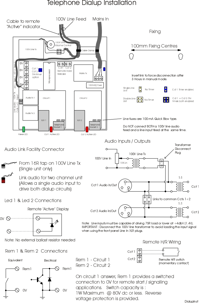
- Connect external Active indicator, remote start and remote hold facilities as required.
- Connect an audio signal to the unit. Note this can be a balanced line level +4dB (1.5V rms) signal via the front panel XLR connector(s) or a 100V signal from a sound system speaker feed. The 100V Line input is an internal connection which can be adjusted for level by adjusting the internal volume control. If using the line level front panel input - disconnect the internal 100V transformer from the circuit board (remove 2 pin plug) to give a louder signal.
- Connect the Dialup unit to a telephone line. Use the adapter supplied to connect both a telephone and the Dialup unit to the telephone line for use in Manual mode.
- Connect the Dialup unit to the UK mains power supply (230V) ideally via the sound system main On/Off switch.
- The green power indicator light illuminates to show the unit has power.
- The red Active light flashes briefly (0.5s) to show the unit is functional. A single flash denotes automatic operation whilst a double flash indicates manual configuration.
- The Dialup unit is now ready for operation.
- Move the switch to the Automatic position. The Dialup unit will automatically answer the next incoming telephone call and connect it to the audio source. The red Active indicator illuminates and stays on until the caller clears the line. In Manual mode, the unit will connect to the telephone line as soon as the switch is moved briefly from Man to the H/R (Hold/Release) position and the red Active light will illuminate. The unit will remain connected until the switch is again moved to the H/R position and held for about 3 seconds (red light goes out) or until the internal 3 hour timer expires. Note that the timer can be disabled by removing the internal facility link. In this mode the unit will remain connected until either the H/R switch is pressed or the power disconnected. Note that in automatic mode, the Dialup, having answered a call, may detect lifting the local receiver handset as a disconnect signal and clear down i.e. go off line thereby cutting off the caller. This is related to loss in the telephone line and is normal.
- Set the unit to automatic and dial from another telephone i.e. a mobile. Have a CD playing slightly louder than normal in the hall. Adjust the Dialup volume level until the signal heard over the mobile remains clear just before it begins to distort or crackle. This is the loudest that the system will go and setup is complete. Note that loudness is related to telephone line losses i.e. how near / far is the local telephone exchange.
- Certain types of exchange (cable) provide a non standard clear down (K Break) signal and prevent the unit from clearing down at the end of a call. In this case you will need to ensure that the sound system main On/Off switch also controls power to the Dialup unit or consider using the unit in manual mode.
The TDS1 Dialup Unit is microprocessor controlled and makes use of surface mount technology to achieve small size together with high reliability. There are no moving parts to wear out and all components are conservatively rated to give a long service life. Warranty is 12 months from invoice date and is RTB (Return To Base). Lightning damage is specifically excluded from the terms of the warranty.
Specification
Power 230Vac 50mA Use a 3 or 5A mains fuse.
Internal Fuses 100mA A/S 20mm mains. 2 x 100mA QB line.
Audio Balanced Line Input : +4dB (1.5V) 600 R source impedance or less.
100 V Line input : Adjust potentiometer to suit available signal level.
REN 1.2
Telephone Connect via BT - BT telephone type plug lead (supplied).
Approvals Meets latest CE requirements.
|
|
© 1994-2026 DTSystems. All Rights Reserved. |
|
Home | Prices | Contact | Terms | Site Map | Telephone Dialup Manual (Original Version) |