Church Induction Loop Systems - AFILS

MAIN PAGES

DTSystems Front Page
Catalogue and Prices
Catalog and Prices USA
Ordering
Auction Goods
Terms & Conditions
Site Map
Links
 

INDUCTION LOOPS

KH Loop Systems
Are they easy to fit?
Frequently asked questions

LOOP DIAGRAMS

Simple layout
Small layout
Larger layout

LOOP THEORY

Simple Explanation
More Detail
Advanced

OTHER

Telephone Dialup Systems
Sound Systems
HiFi Section
Environmental Section

CHURCH INDUCTION LOOP SYSTEMS - AFILS

Audio Frequency Induction Loops - The Law Has Changed Church Loop Systems - In the UK, Public venues like this one **MUST** have a standards compliant Audio Frequency Induction Loop fitted - by law
Did you know that in the UK it is now MANDATORY (Under the terms of the Disability Discrimination Act) for ALL public buildings to make adequate provision for the disabled (eg wheelchair access) and specifically, the hearing impaired?

Did you also know that the international standard (IEC118-4) has recently been revised and that your loop system now needs to be louder?


Note the term MANDATORY. In other words, those responsible for running and maintaining the building, MUST make adequate provisions for the hearing impaired or they can be taken to court and prosecuted for non-compliance. Simply ignoring the problem altogether, or installing a badly engineered or non compliant system, is just not acceptable and is, quite simply, breaking the law. Fortunately, the solution to this issue is neither too expensive nor too complicated.

STANDARDS: All AFILS must be installed in such a way as to be of use to the end user and to meet the requirements of IEC118-4 which is a world standard for Induction Loop systems. However, you MUST take expert advice BEFORE buying a loop "kit" unless you know what the problems might be. You (or your expert) need to check for:

  • Background Noise and Interference - Poorly installed mains cables or a nearby power grid line may make your loop system useless.
  • Construction of the room in which the loop is to be installed - Metal structures in the floor, walls or ceiling WILL affect your loop and MUST be part of the design calculations.
  • Proximity of adjacent loop systems - Will they interfere with each other?

BEFORE ordering any equipment, make SURE you have answers to the points above.


Advice Center

Fortunately, the solution to the problem is neither too costly nor expensive and can be retro fitted to most locations. Take a look at York Clifton who have a standards compliant Phased Array (finished 2008). Just complete the form below and we will get back to you with a solution to your AFILS problem. You may wish to get an ILR3 portable receiver to check your loop system works.
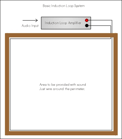
Induction Loop Systems (AFILS) - Request For Design or Additional Information

Please be accurate when entering information as the answers you get will only be as good as the information you supply. NONE OF YOUR INFORMATION WILL BE SOLD OR PASSED ON TO THIRD PARTY MAILING COMPANIES. Full explanations are available for each of the entries you fill in - Click on any blue words for further help.

Your NAME* Your EMAIL*

Project Name or reference


MEASUREMENTS - All measurements in: Metres Feet - Choose (Note: use 13'6" format).

Loop dimensions Width Length
Convert the area to a regular shape
What height is the ceiling?
Floor to ceiling dimension
Use flat copper foil? NoYes
Fits under a carpet or floorcovering

BUILDING CONSTRUCTION How much metalwork is contained within the area covered by the loop wiring? **CRITICAL**
If you have a cement floor and suspended ceiling tick box 1. If a wooden building with no metal, tick box 4 etc.

How much metalwork?: Floor & Ceiling Floor OnlyCeiling Only No Metal

Any other information? ie - Wooden floor 3' above reinforced slab, Equipment to be rack mounted etc.

* Required Fields - Please enter details carefully - We can't reply if your email address is wrong!

A scale plan of the area to be covered - clearly marked with the loop boundary would also be helpful - Remember to add the reference number or project name. You can Email.


LOOP DESIGN ACCURACY....Back to form

If you take the time to read all the information below, you will come to realise that installing a loop system is really easy - the secret of getting it right is in the initial design. Some installation companies understand this but many others do not and will install simple perimeter or voltage loop (multi-turn) systems inappropriately, leaving you, the client to deal with any fallout.

DISABILITY DISCRIMINATION ACT (DDA)

Many countries are begining to take the issue of disability very seriously and some like the UK and US have legislation in place to make it a criminal offense NOT to cater for such ones. In the context of hearing, the DDA (UK) has major implications for anyone involved in the design or running of areas used by either the general public or specific meeting places. So for example if you are say one of the trustees of your local church or meeting hall, you have a responsibility, in law, to ensure the disabled are not discriminated against. In other words that they have an equal chance to hear what is happening just the same as a normal hearing person.

In a meeting hall context, this is achieved easier and cheaper than any other comparable method by using an AFILS (Audio Frequency Induction Loop System) tied into the sound system. Anyone with a hearing aid can switch to the T position and hear the sound direct with no distracting background noises. Even better, there are no extra receivers or headphones to carry around advertising that a person is hard of hearing - AFILS are very discreet and effective.

INTERNATIONAL STANDARDS

However, just having a loop system is not enough - it MUST meet the appropriate standards (EN60118-4 formerly BS6083 or IE118-4) otherwise there is no point in having it! The standards ensure that loop signals are a uniform volume across all the area contained by the loop wiring, are loud enough to meet a defined standard and can be heard clearly by users. In general terms, old fashioned voltage loops with multiple turns of wire just DO NOT meet the standards and need to be replaced or upgraded immediately. Trustees or building designers have a responsibility enshrined in law to ensure compliance with the standards under the terms of the DDA.

LOOP INPUTS....Back to form

Inputs to a loop system can be from almost anything - a microphone, Public Address (PA) system, music mixer or TV / home theatre system. However, the quality of signal heard through the loop system is only as good as that going in through the input. So for example sticking a boundary (plate) microphone on a wall or ceiling in a room and expecting it to pick up all conversations in the room just will not work!! It will pick up everything - all conversations, noises from outside, noises transmitted through the building fabric, air con systems and anything else. In short - lots of unwanted sound. The result will be a jumble which gets transmitted through the loop system - no good. Some thought must go into where the sound sources are and then picking up the specific bits. Usually the best solutions to this puzzle are a few well placed microphones feeding through an automatic mixing system and then into the loop amplifier. Then just the wanted sounds are amplified and the loop system works really well.

For the home type environment, loop systems can be a real boon as the volume is no longer determined by the person with the worst hearing in the room! Volume levels can be restored to normal and anyone hard of hearing can listen as loud as they wish via the loop system....more.

OLD FASHIONED VOLTAGE LOOPS NB - As supplied in ALL current quickly built KH sound kits

In the early days of AFILS and before specialist equipment was available, the accepted method of fitting a loop system was to throw a multicore cable around the perimeter of a room or building, wire all the turns in series and then connect it to an ordinary hi-fi amplifier. NO GOOD!!! Due to various factors (cable inductance, lack of current, reactive amplifier loads, building metal content etc.) this sort of worked in places and not in others. Such systems almost always fail to meet the standards and have been almost universally replaced by SINGLE turn loops fed from CURRENT amplifiers - specially designed equipment. All our designs use current loop technology and in fact the best equipment currently available made by Ampetronic.

ADDITIONAL INFORMATION

YOUR DETAILS:....Back to form

  • Your Name: This is for our records so that we can deal with you personally.

  • Your Email: So we can contact you - Please make SURE that you enter this correctly as we won't be able to respond to your request if it is wrong.

  • Project Name or Reference: Every single design will be different - that is why this service is SO unique as it takes account of literally hundreds of possible variations to produce the BEST possible design based on your data.

  • Measurements: All measurements MUST BE OF THE SAME TYPE - Either in Metres or Feet - Check the box to tell us which measurements you want to use. It is important that measurements are accurate. The reference point for all calculations is floor level (0) so be aware that you CAN have negative measurements - ie below floor level. So a dimension of -2.3 would put you down in the basement somewhere! Loop wiring can be installed in plastic piping (for mechanical protection) in the building foundations or alternatively, above the ceiling dependant upon meeting design dimension criterion. You may also install the loop wiring outside the building to encircle a space within. Flat foil cable can be hidden behind dado or picture rails (behind wood mouldings or trim) or behind wallpaper or borders.

  • Loop Dimensions: This loop designer follows the industry standard of simplifying the area to be covered by the loop system into a simple square or rectangular shape. If your area is not a uniform shape, then simply draw the shape out to scale and overlay it with a regular shape so that the area covered is the same. Then measure the two sides and enter the dimensions. You can send a scale diagram if you wish for us to check. Highly complex shapes though may need special treatment.

  • Ceiling Height: Quite simply the distance between floor and ceiling.

  • Tails: Tails are the ends of the loop wiring that go from the amplifier to the loop itself. For a perimeter loop installed at floor level, they will probably be quite short, whilst for a loop installed at ceiling height they could be longer. In all cases, try to keep the distance between amplifier and loop to an absolute minimum. Tails introduce additional unwanted losses due to the resistance of the extra cable. Installations using flat copper foil are assumed to be connected to the amplifiers via 1.5mm˛ (14AWG) cables or thicker soldered directly to the ends of the foils. You should always twist the feed cables together quite tightly to reduce losses and unwanted fields.

  • Flat Foil: This is a type of wire that can be used in difficult situations. It has a wide but very thin (0.5mm 0.02") profile and can be used to install loop wiring under carpets, behind plaster or even stuck to the wall behind a suitable trim. It comes in 50m (164') lengths and is insulated with a tough plastic coating. Warning tape is available in the same lengths that can be used to stick the foil to the floor. On bare concrete surfaces, the manufacturer advises sealing the concrete prior to installing the tape as an additional protection. Join sections together by stripping a small amount of insulation from either end and soldering together. Tails (connections to the amplifier) should be 1.5mm˛ or thicker and soldered to each end of the loop foil.

  • Loop Listening Height: Also known as Loop Plane Level (LPL). This is the average height from the floor to the hearing aid. The listening plane is described as the average height at which a hearing aid may be (head height) whilst listening to the loop signal. For someone sat down on a chair this is usually 1.2m (3'11"). Note that this level may change such as in a lecture theatre with stepped seating. In this case the LPL and hence loop cabling would follow the contours of the seating to maintain the same relative distance.....Back to form

  • Loop Installation Height: This ONLY applies where your area to be looped has NO metal at all. It is VERY critical and needs to be worked out precisely. If you fit the wiring at the wrong height you will:

    • Have an uneven signal - loud in some places and quiet in others.
    • Might overload users hearing aids - will result in distortion / poor clarity.
    • May need significantly more power to produce adequate volume - translates to increased amplifier size / cost.
    • Defeat the object of installing the loop in the first place if results are patchy.

    In fact there are TWO narrow bands where the loop wiring can be fitted within any room, one ABOVE the Listening Plane Level (LPL) and the other BELOW it (see above). The distance between the LPL and loop wire is calculated from the dimensions of the room and the type of installation. For a Perimeter loop, the ideal position above or below head height (assumed to be the LPL height) is 12% to 16% of the loop width (where width is the smallest dimension). This distance MAY be increased (with additional amplifier power) but must NEVER be decreased. THE LOOP MUST NEVER EVER BE INSTALLED AT THE SAME HEIGHT AS THE RECEIVER (HEAD HEIGHT)!

    You can input a specific height at which you plan to install the loop wiring, or you can tick a box and we will tell you the two ideal positions. NOTE: If you tick the box AND enter a specific height, we will always use the recommended heights (ie the tick box) in preference to your entered height. Uncheck the tick box to calculate based on your height input. What you CAN'T do though is order a system based on our recommendations and then install the wiring at a different height - it will not work properly!

    BUILDING CONSTRUCTION....Back to form

    It is essential that you understand the relationship between metalwork and induction loops otherwise you may install a system that simply does not work, sounds poor or fails to meet standards. The amount of metalwork (if any) decides how the loop will be designed and is absolutely fundamental to achieving a workable system.

  • Metalwork: - Critical to understand this

    Any metal (grid or sheet) that is contained within the area where the loop is to be installed will have an effect on loop design and performance if:

    • It is arranged in electrically conductive paths ie reinforced concrete floors, metal ceiling or floor tiles, foil backed plasterboard and some suspended / false ceilings. Each of these contains metal arranged into closed circuits and any magnetic field crossing it will generate a current within that closed circuit. Lots of metal - lots of circuits. Each circuit drains energy from the loop system - and so more energy has to be applied to overcome these losses. Compounded with this is the fact that energy losses are frequency selective - in other words high frequencies tend to be absorbed more quickly. The effect is for the audio received through the loop to sound as though you had placed a thick blanket across your hi-fi speakers - muffled and indistinct.

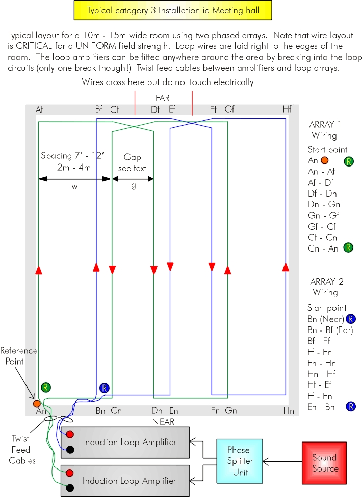
    So to recap - The main consideration is the amount of metalwork containing closed paths within the area covered by the loop. Any metalwork that is away from the area enclosed by the loop cables can be ignored. Open ended metal structures such as supports or beams can also be ignored (no closed circuit).

    In simple terms, the less metal the better.

    No significant structural metalwork or metal in floor or ceiling

    This is the 'simplest' type of installation. Older brick built buildings or timberframe on post construction are typical of this type of construction. Most small home or domestic loops will be this type as will large Cathedrals (no metalwork).

    Building with limited metalwork - metalwork in the ceiling or floor but NOT BOTH

    Losses due to metalwork in this type of building can be significant and need a more rigorous approach if design targets are to be achieved and a uniform loop field produced. The usual approach is to fit a loop away from the location of the metal. However, it may be easier and certainly give more predictable results to plan for a phased array design.

    Metalwork in Floor AND Ceiling or unknown construction

    This is the installation of choice for most meeting halls such as Chapels, Kingdom Halls, Small Churches, Small Conference Centres, Lecture Theatres etc. up to large 1000 seat++ venues. This design uses a "Phased Array" technique which maintains an even loop signal under difficult conditions. The use of flat copper foil may be useful in this case as the loop wiring has to cross the room in a number of places and foil can be installed under a carpet. Alternatively, the loop wiring may be buried in the screed before the floor is finished or above a suspended ceiling using ordinary wire contained within plastic conduit.

    GENERAL....Back to form

    Interference: Are there any potential sources of interference which may be picked up by a hearing aid switched to the T position?

    Very infrequently, a particular location has a problem with interference which can be picked up by a hearing aid user. Sources of interference are: electrical supply sub-stations, large motors, High Voltage wiring, electric railways, CRT monitors or various other sources including poor mains supply wiring technique (split wiring using single cables). The best test is to get someone with a hearing aid switched to T to listen in the proposed loop area. If no hum or interference is apparent at normal listening levels when all normal electrical services are operating, then it is unlikely that any problem will arise. Otherwise, investigate further and isolate / remove the source of interference.

    Other Close Proximity Loop Systems: It is possible to hear a typical loop system up to three times the loop area away. If there is another loop system within the distance and both loops are to be used at the same time, special arrangements need to be made which fall outside this design service. You need to seek additional assistance.

    Confidentiality: In some situations ie interview booths, it may be desirable to limit the distance the loop signal travels to prevent overhearing. If this is the case, you need to seek further assistance.


    We hope you found the site interesting, well presented and above all, informative. Thanks for visiting and please feel free to link to us or recommend us to others.

  •     © 1994-2008 DTSystems. All Rights Reserved.
        Designers and Manufacturers of Electronic Equipment.
    Home | Prices | Contact | Terms | Site Map | Church Induction Loop Systems - AFILS